Full Wave Bridge Rectifier / Simulate full wave bridge rectifier with proteus - YouTube : This electronics video tutorial provides a basic introduction into full wave bridge rectifiers which are used to convert an ac sine wave signal into a.
Full Wave Bridge Rectifier / Simulate full wave bridge rectifier with proteus - YouTube : This electronics video tutorial provides a basic introduction into full wave bridge rectifiers which are used to convert an ac sine wave signal into a.. The process of converting the ac current into dc current is called rectification. Why is a full wave bridge rectifier better than a full wave center tapped rectifier? The step down transformer reduces the high voltage ac into low amplitude ac supply and. Voltage to be rectified is applied through a power transformer tr1 across one diagonal of the bridge while the load resistor rl is connected across the. Full wave rectifier consists of two diodes and one step down transformer which is centre tapped.
Full wave bridge rectifier circuit. Even full wave bridge rectifiers are used more than other rectifiers. Whereas, the load resistor rl is connected across the. Introductionthis intractable page will guide you through all the steps necessary to build a full wave bridge rectifier. For this purpose, 17v ac (peak value) power is converted.
THE ELECTRIC ONLINE: Basic Rectifier Circuit from 2.bp.blogspot.com The four diodes labeled d1 to d4 are arranged in series pairs with only two diodes conducting current during each half cycle. A bridge rectifier is an arrangement of four diodes in a bridge circuit configuration which provides the same output polarity for either input polarity. Principle of full wave bridge rectifier. The circuit form a bridge connecting the four diodes the ac supply which is to be rectified is applied diagonally to the opposite ends of the bridge. In full wave bridge rectifier, an ordinary transformer is used in place of a center tapped transformer. Introductionthis intractable page will guide you through all the steps necessary to build a full wave bridge rectifier. Between other two ends of the bridge. The full wave bridge rectifier circuit contains four diodes d1 , d2,d3 and d4, connected to form a bridge as shown in fig(4).
Nte electronics nte53016 silicon bridge rectifier, full wave, single phase, low profile epoxy case, 50 amps maximum output current, 200v maximum recurrent peak reverse voltage.
Nte electronics nte53016 silicon bridge rectifier, full wave, single phase, low profile epoxy case, 50 amps maximum output current, 200v maximum recurrent peak reverse voltage. Many applications require direct current, dc. Full wave bridge rectifier shown in figure 1 uses four diodes d1, d2, d3 and d4 connected to form a bridge circuit and hence the name. The important uses of full wave bridge rectifier are given below. Further full wave rectifiers are designed in two ways: Even full wave bridge rectifiers are used more than other rectifiers. For a full bridge rectifier also, the piv rating calculation is the same as half wave rectifier, that is: Diode rectifier circuits half wave rectifier full wave rectifier two diode full wave rectifier full wave bridge rectifier synchronous rectifier. Full wave bridge rectifiers and center tapped full wave rectifiers. We can improve the average dc output of the rectifier while at the same time reducing. A full wave rectifier is a circuit arrangement which makes use of both half cycles of input alternating current (ac) and converts them to direct current (dc). It is useful in converting ac current to dc current.parts (with purchasing links)(pictures of the parts are included with corresp… You must also consider the switching topology used to see why a full wave bridge rectifier may or may not make sense to.
Depending on the polarity of the source, the current will flow through two of the diodes. Supply to be rectified is applied to the diagonally opposite ends of the bridge through the transformer. Full wave bridge rectifiers have the disadvantage of having two diode drops in normal use instead of just one so when currents are high this can be a major source of power waste. For a full bridge rectifier also, the piv rating calculation is the same as half wave rectifier, that is: As far as i know both do the same thing while the bridge is using two more diodes making it more expensive.
Rectifier Circuits | Diodes and Rectifiers | Electronics ... from sub.allaboutcircuits.com In full wave bridge rectifier, an ordinary transformer is used in place of a center tapped transformer. Full wave bridge rectifiers have the disadvantage of having two diode drops in normal use instead of just one so when currents are high this can be a major source of power waste. The bridge rectifier uses four diodes connected as shown in figure. Nte electronics nte53016 silicon bridge rectifier, full wave, single phase, low profile epoxy case, 50 amps maximum output current, 200v maximum recurrent peak reverse voltage. The primary winding of the transformer is supplied with a sinusoidal supply. Between other two ends of the bridge. You must also consider the switching topology used to see why a full wave bridge rectifier may or may not make sense to. Because the load is always on half of the secondary winding.
Full wave bridge rectifiers are widely used for the low cost of diodes than center tapped transformers, high efficiency, lightweight, etc.
Whereas, the load resistor rl is connected across the. As far as i know both do the same thing while the bridge is using two more diodes making it more expensive. Full wave bridge rectifier shown in figure 1 uses four diodes d1, d2, d3 and d4 connected to form a bridge circuit and hence the name. It is useful in converting ac current to dc current.parts (with purchasing links)(pictures of the parts are included with corresp… Bridge rectifier overall these three bridge rectifier gives better efficiency and ripple free dc. Piv ≥ vm, since vm is the total voltage that's applied to the connected load as depicted in the following figure. Full wave bridge rectifiers have the disadvantage of having two diode drops in normal use instead of just one so when currents are high this can be a major source of power waste. For a full bridge rectifier also, the piv rating calculation is the same as half wave rectifier, that is: The four diodes labeled d1 to d4 are arranged in series pairs with only two diodes conducting current during each half cycle. The circuit diagram is as follows. Introductionthis intractable page will guide you through all the steps necessary to build a full wave bridge rectifier. What is the difference between the full wave rectifier and the full wave bridge rectifier? Depending on the polarity of the source, the current will flow through two of the diodes.
A bridge rectifier is an arrangement of four diodes in a bridge circuit configuration which provides the same output polarity for either input polarity. The process of converting the ac current into dc current is called rectification. Although the half wave rectifier finds applications in signal and peak detection, it is not widely used in power rectification. The full wave bridge rectifier circuit contains four diodes d1 , d2,d3 and d4, connected to form a bridge as shown in fig(4). Rectification can be achieved by using a single diode or group of diodes.
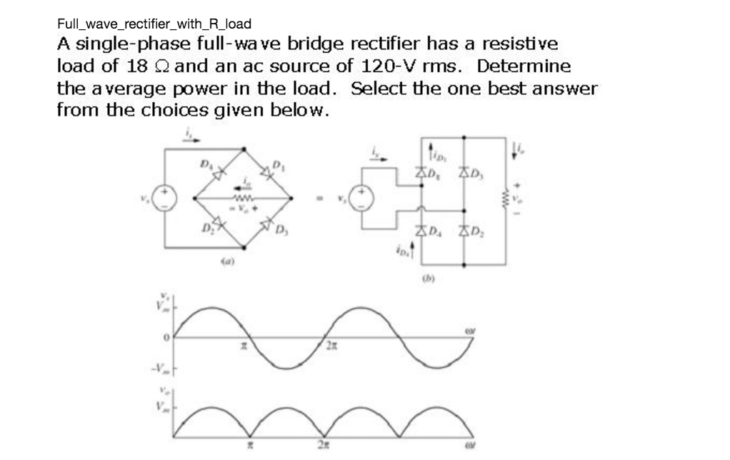
Solved: A Single-phase Full-wave Bridge Rectifier Has A Re ... from d2vlcm61l7u1fs.cloudfront.net Although the half wave rectifier finds applications in signal and peak detection, it is not widely used in power rectification. Between other two ends of the bridge. Whereas, the load resistor rl is connected across the. Diode rectifier circuits half wave rectifier full wave rectifier two diode full wave rectifier full wave bridge rectifier synchronous rectifier. In other words what do we gain if we use the bridge? Because the load is always on half of the secondary winding. The step down transformer reduces the high voltage ac into low amplitude ac supply and. What is the difference between the full wave rectifier and the full wave bridge rectifier?
Full wave bridge rectifiers and center tapped full wave rectifiers.
Depending on the polarity of the source, the current will flow through two of the diodes. Although the half wave rectifier finds applications in signal and peak detection, it is not widely used in power rectification. Introductionthis intractable page will guide you through all the steps necessary to build a full wave bridge rectifier. The circuit diagram is as follows. A full wave rectifier is a circuit arrangement which makes use of both half cycles of input alternating current (ac) and converts them to direct current (dc). For a full bridge rectifier also, the piv rating calculation is the same as half wave rectifier, that is: Many applications require direct current, dc. Rectification can be achieved by using a single diode or group of diodes. Because the load is always on half of the secondary winding. Why is a full wave bridge rectifier better than a full wave center tapped rectifier? For this purpose, 17v ac (peak value) power is converted. Full wave bridge rectifier shown in figure 1 uses four diodes d1, d2, d3 and d4 connected to form a bridge circuit and hence the name. Nte electronics nte53016 silicon bridge rectifier, full wave, single phase, low profile epoxy case, 50 amps maximum output current, 200v maximum recurrent peak reverse voltage.
You have just read the article entitled Full Wave Bridge Rectifier / Simulate full wave bridge rectifier with proteus - YouTube : This electronics video tutorial provides a basic introduction into full wave bridge rectifiers which are used to convert an ac sine wave signal into a.. You can also bookmark this page with the URL : https://vasoltsan.blogspot.com/2021/05/full-wave-bridge-rectifier-simulate.html
Share Awesome
Belum ada Komentar untuk "Full Wave Bridge Rectifier / Simulate full wave bridge rectifier with proteus - YouTube : This electronics video tutorial provides a basic introduction into full wave bridge rectifiers which are used to convert an ac sine wave signal into a."


Belum ada Komentar untuk "Full Wave Bridge Rectifier / Simulate full wave bridge rectifier with proteus - YouTube : This electronics video tutorial provides a basic introduction into full wave bridge rectifiers which are used to convert an ac sine wave signal into a."
Posting Komentar